quality-policy-img

Quality Policy

At Speedofer Components Pvt. Ltd., our commitment to excellence is reflected in our Quality Policy. We are dedicated to manufacturing products that align with the specific requirements of our customers. Additionally, our pledge extends beyond the production phase, as we are equally devoted to providing outstanding after-sales service. We believe in achieving this through a continuous process of improvement within our Quality Management system.

Quality Objectives

Our pursuit of excellence is guided by specific Quality Objectives, including :-

Adapting to Changing Technology :- We are committed to staying abreast of the ever-evolving technology landscape in the soft ferrite core industry. This commitment drives us to continually enhance our Quality Measurement System to meet the challenges posed by changing technologies.

Continuous Improvement :- Embracing a philosophy of continuous improvement, we strive to refine and enhance our processes to ensure the highest quality in our soft ferrite core products. This dedication is pivotal in maintaining our position at the forefront of technological advancements.

 quality-objectives-img
policy-img

Company Philosophy

At Speedofer Components Pvt. Ltd., our Company Philosophy revolves around the principles of continual improvement and adapting to technological changes in the soft ferrite core industry. We emphasize the creation of a healthy working environment for our employees and nurturing strong relationships with our business partners.
In essence, our Company Philosophy encapsulates our commitment to growth, innovation, and the creation of a positive and sustainable impact within the soft ferrite core industry. Speedofer Components Pvt. Ltd. is dedicated to being a dynamic force that embraces change, ensures quality, and builds lasting relationships.

Definitions & Equations

Definitions :-
1) Initial Permeability, µi
This is the limit value of B/H where H is indefinitely close to
zero at the initial magnetization curve of a ferromagnetic substance. µi = 1 lim B µ0 (H--->0) H Where µ0 Permeability in Vacuum (4πx10-7H/m) H Magnetic Field Strength (A/m) B Magnetic Flux Density (T) 2) Effective Permeability, µe Effective Permeability of a core forming a closed circuit where
leakage flux is negligibly small. µe = Le µ0AeN2 Where L Self Inductance of Coil with Core (H) N Number of Turns in Coil Le Effective Magnetic Path Length of Core (m) Ae Effective cross sectional area of Core (m2) 3) Saturation Flux Density, Bs (T) Saturation flux density is the maximum attainable flux density when a very high magnetic field is applied to a soft magnetic material as shown in the figure below. 4) Residual Magnetic Flux Density, Br (T) This is the amount of residual magnetic flux density retained by the
core after the magnetic field is weakened and finally removed, as shown in the figure above. 5) Coercivity, Hc (A/m) This is the strength of the magnetic field whereby the residual flux
density becomes zero under the intensification in the opposite direction of the magnetic field, as shown in the figure above. 6) Loss Factor, tanδ The loss factor can be split up into three parts as tanδ= tanδh+
tanδe+ tanδr Where tanδh Hysteresis loss tanδe Eddy-current loss tanδr Residual loss 7) Relative Loss Factor, tanδ/µ This is the amount of loss per unit permeability and is defined as
below. tanδ/µi (for magnetic material) tanδ/µe (where gaps are added to the magnetic circuit) 8) Hysteresis Material Constant, ηB (10-6/mT) Hysteresis material constant characterizes the change of the
hysteresis loss of the material when the flux density is increased. ηB = Δtanδ µeΔB Where tanδ Loss factor µe Effective Permeability B Magnetic Flux Density (mT)
9) Temperature Coefficient, αµ (K-1)	
This is the fractional difference of permeability per oK in a 
temperature range from T1 to T2 (T2 >T1) αµ = (µ2-µ1)/µ1(T2-T1) Where µ1 Permeability at temperature T1 µ2 permeability at temperature T2 10) Relative Temperature Coefficient, αµr (K-1) This is the temperature coefficient per unit permeability αµr= (µ2-µ1)/µ12(T2-T1) The temperature coefficient of an actual core is obtained from below αµ = aµpx µe 11) Curie Temperature, Tc (℃) The Curie temperature Tc is defined as the temperature at which the magnetic core changes from the ferromagnetic to the paramagnetic state. 12) Resistivity, ρ (Ωm) This is the electrical resistance per unit length and cross-sectional
area of a magnetic core. 13) Density, d (kg/ms3) This is the weight per unit volume of a magnetic core. d = W/V Where: W Weight of magnetic core (kg) V Volume of magnetic core (m3) 14) Power Loss density, Pc (kw/m3) Power loss denotes the loss under a magnetization condition featuring
a high frequency and a large amplitude. Operating magnetic flux density is generally expressed for a sinusoidal wave as below. Bm = E/(4.44f NAe) Where Bm Peak value of magnetic flux density (T) EV oltage effective value applied to test coil (V) f Frequency (Hz) N Number of coil turns Ae Effective cross-sectional area of core (m2) 15) Inductance Factor, AL (nH/N2) AL= L/N2 Where AL Self-inductance of coil with core (H) N Number of coil turns The inductance factor is generally united by 10-9H/N2 (nH/N2)
Equations :-
1)  µi(Initial Permeability)
µi =  1	 lim	    ΔB	 	
µ0      (ΔH->0)    (ΔH) 
                                                                                                                                                                                               
   µ0  (4πx10-7H/m) 

2) Toroidal Permeability
µ =	   1000Lle	 	 	 	 	 	 
     4πN2Ae	 	 	 	 	 	 	 	 	 	 	 	 	 	 	                                                                                                         
Where    L	 Inductance(µH) 	 
      µ	 Permeability	
      N	 No of Turns	
      Ae	 Effective cross sectional area (cm2)
      le	 Effective Magnetic Path Length (cm) 	
      
3) µe Effective Permeability
µe =	   1000L	 	 	 	 	 	   	 	 	 	 	 
     4πN2                
Σ =	l	 
 A	                                                                                                       
Where    L	 Inductance(µH) 	 
      µ	 Permeability	
      N	 No of Turns	
      l	 Effective Magnetic Path Length (cm) 	
      A	 Effective cross sectional area (cm2)
          
4) µe AL Inductance Factor             
AL= L/N2
AL: nH/N2	Inductance Factor
Where	       L	Inductance
         N	No of Turns 
5) Magnetic Field Strength
H =	   0.4πNl	 	 	 	 	 	 
    le	 	 	 	 	 	 	 	 	 	 	 	 	 	 	                                                                                                                  
Where    H	 Magnetic Force(Oe) 	 
    N	 No of Turns	
    l	 Current(A)	
    le	 Effective Magnetic Path Length (cm)                   
            
6) Peak Ac Flux Density
Bmax =	   Erms108	 	 	 	 	 	 
     4.44fAeN	 	 	 	 	 	 	 	 	 	 	 	 	 	 	 
                                                                                                                                    
Where    B	 Peak Ac Flux Density (Gauss)
      F	 Frequency (Hz)
      Ae	 Effective Cross-Sectional Area cm2 	
      Erms	 RMS Voltage (V) 	

7) LeEffective Magnetic Path Length of Toroidal Cores 
le =	   π(OD_ID)	 	 	 	 	 	 
     	
        ln     OD 	 
             (ID)	  	 	 	 	 	 	 	 	 	 	 	 	 	 	 
                                                                                                                                    
Where    OD	 Outer Diameter (cm) 	 
      ID	 Inner Diameter (cm)	
      le	 Effective Magnetic Path Length (cm) 
      
8) AeEffective Cross-Sectional Area 
Ae =	   (OD_ID) xHtXK	 	 
     2	                                                                                                         
Where    OD	 Outer Diameter (cm) 	 
      ID	 Inner Diameter (cm)	
      HT	 Height (cm)	
      K	 Coefficent Relative to the Shape of the edges (cm)	
      
9) Quality Factor (Q)
Q =	   ωL 	 
     Rdc+Rac+Rcd	                                                                                                         
Where    Q	 Quality Factor 	 
      L	 Inductance (H)	
      ω=2πf  Frequency (Hz)	
      Rdc	 Dc Winding Resistance (Ω)	
      Rac	 Resistance due to core loss (Ω)	
      Rcd	 Resistance due to dielectric loss of Winding (Ω)	
            

RoHS Certificates

SFA05 Grade
SFA05 Grade RoHS Compliance
SFA10L Grade
SFA10L Grade RoHS Compliance
SFP4 Grade
SFP4 Grade RoHS
Compliance
SFP4 Grade
SFP95 Grade RoHS Compliance

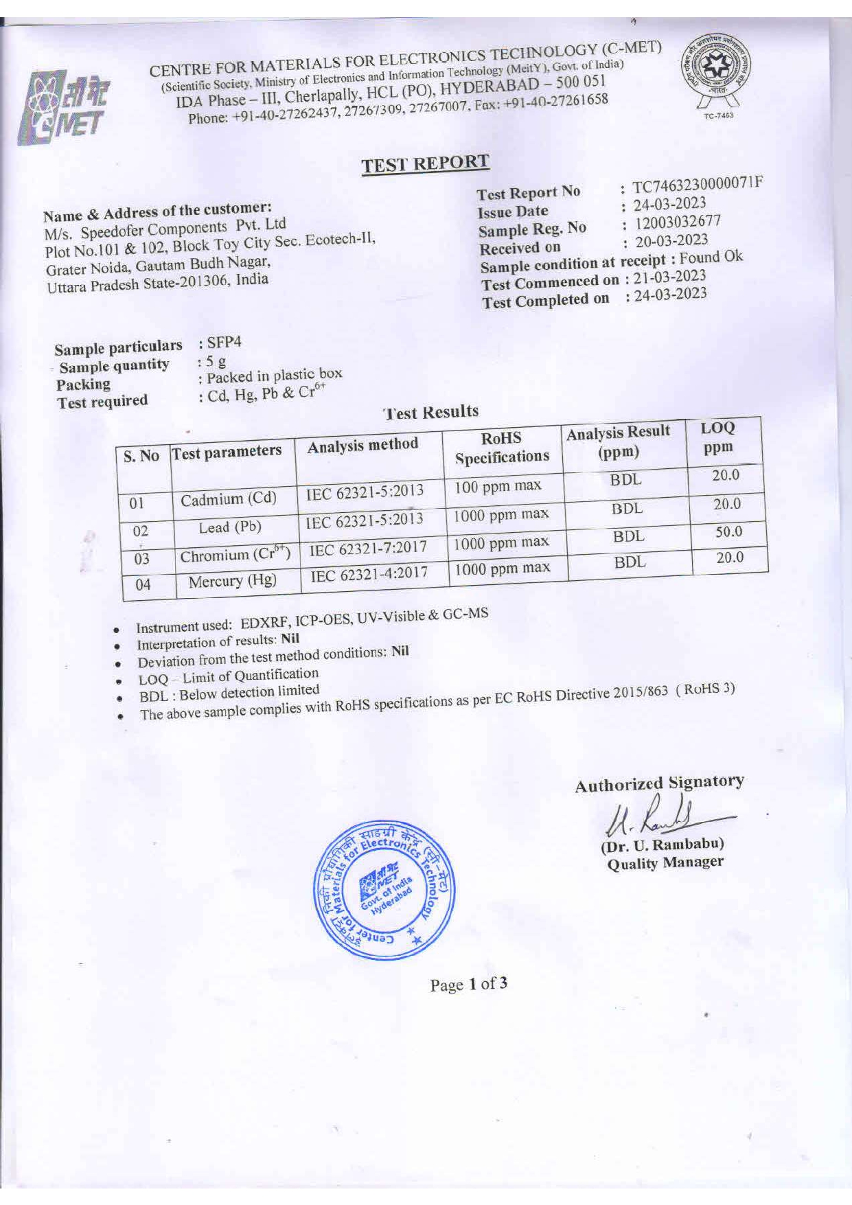
Speedofer Certifications

OHSAS

OHSAS

EMS

Ems

QMS

QMS

DUNS

DUNS
×
Modal Image